


Description
FLEX & RIGID-FLEX PCB DATA REQUIREMENTS AND FABRICATION INSTRUCTIONS
Below you will find the minimum data information requirements needed to place your flex or rigid-flex circuit board order. The purpose of this webpage is to describe the minimum data and information required to generate the tooling for your order.
The minimum required data and information set can be broken down into the two categories: Data Requirements and Fabrication Instructions.
|
Flex & Rigid-Flex Data Requirements
Date set consists of the traditional data package which must include the following:
Gerber Data in the following formats:
- Gerber files with aperture lists
- DXF can be used requires an approval prior to production
- ODB++ format
See our blog post on rigid-flex PCB gerber layout requirements for more information.
Drill Data in the following formats:
- Excellon 1
- Excellon 2
Also acceptable is ODB++ data. ODB++ will be supplied as a single file, usually with the extension of .tgz. ODB++ contains all the required board and drill information.
* Note: Any other data formats need to be reviewed and approved by Epec Engineering before the order can be placed.
Flex & Rigid-Flex Fabrication Instructions
The fabrication instructions should contain all relevant information required to tool and build the part including:
- Material Stackup: Defining all materials, copper weights, Coverlay/Soldermask(s), and finished thickness requirements with tolerance(s)
- IPC 6013 Manufacturing Class 2 or 3 (Class 1 not available)
- Hole sizes with tolerances, and plating information
- Board outline detail with all required dimensions and tolerances
- Hole or feature to edge dimensions
- Surface finish requirements
- Silkscreen requirements
- Min. Bend Radius requirement(s)
- ZIF Connector make(s) & part number(s) that the design connects to (if utilized)
- Technical contact information
- Any additional requirements (i.e. impedance control, plugged vias, stiffeners, PSA etc.)
Fabrication instructions may be supplied in the following formats:
Fabrication Drawing formats:
- Adobe Acrobat (.pdf)
- Gerber
- RS274X
- HPGL
- AutoCAD (.DWG or .DXF)
- Graphic file (.JPG, .GIF, .TIF, etc.)
- ODB++
- Array configurations – tab or scored preference
Notes, read me files, and/or customer specification
FLEX CIRCUIT TERMINATION METHODS
There are a variety of terminations for flex circuits and we can provide all of these as standard manufacturing process. Adding connectors and other minor component assembly is a common practice when producing a flex circuit. List below are some of the common termination methods used in flex circuit technologies.
ZIF Connectors
A ZIF (zero insertion force) is a type of connector that requires very little force for insertion. They allow for top and bottom contact options, vertical and right angle orientations, surface mount and through hole terminations.
Contact spacing options are allowed down to 0.2mm pitch. Using a ZIF connector eliminates the need for a mating connector. The flex circuit end “mates” into the connector usually located on the rigid board. The ZIF contacts also allow for repeated cycling with minimal wear.
Thru-Hole Connectors or Surface Mount Connectors
Thru-hole or surface mount are the traditionally technology that are used in today’s printed circuit boards. Right angle, Co-Planar, Parallel, and many others options are available.
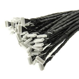
Crimped Contacts & Displacement Connectors
- Contacts are crimped through the dielectric material into the copper conductor.
- Contacts are available for .100″ (2.54mm) or .050″ (1.27mm).
- Centerline housings can also be added to encapsulate the contact.
FLEX & RIGID-FLEX CIRCUIT BENEFITS
Flex and Rigid-Flex circuits gives the ability to design your circuitry to fit the device, instead of building a device to fit the circuit board. They are designed for the rigors of aerospace, medical and military applications, with dependable reliability.
Flex circuits offer multiple advantages for anyone considering to use this technology in a future project or if you’re trying to decide on re-engineering your current design. Below you will find some key benefits of using flex and rigid-flex circuit technology.
For more information see our blog post on Why You Should Use Flex Circuits.
Package Size & Weight Reduction
Combination of design freedom, space, weight and component savings can reduce packaging requirements significantly when using flex circuits as compared to other solutions.
- Flexible circuit boards fit where no other solutions can.
- Flexible circuit boards are thin and light weight which enables a substantial packaging size reduction.
- They have the ability to be folded or creased and positioned into the smallest areas makes miniaturization of many devices possible.
- Space requirements can be minimized by applying the freedom of 3D packaging geometry.
- Utilizing a flex circuit solution into your design can offer a substantial weight reduction benefit over using wires and wire harnesses.
- Flexible circuits can be used to replace wiring reduces the errors common in hand wired assemblies.
Reliability & Durability
- Increased reliability by eliminating interface connections (solder joints, connectors, contact crimps etc.).
- The fewer number of interconnects, the fewer the sources of potential failure.
- Rigid-Flex technology which integrates both a flex circuit and a rigid PCB further reduces the number of interconnects.
- Flex circuit’s ductility and low mass will reduce the impact of vibration and shock and improve performance.
- The exceptional thermal stability of polyimide allows the circuit to withstand applications with extreme heat, as the materials excellent thermal stability provides a better base for surface mounting than traditional boards. Because the compliant base film places less stress on soldered joints, thermal mismatch is less likely to occur.
- Used extensively in high reliability military and medical applications.
Cost Savings
- Thin and flexible polyimide film requires a much smaller area, reducing the overall finished assembly packaging size and material requirement costs.
- Reduced assembly costs are also seen as fewer parts are needed for the final assembled product.
- A simplified PCB assembly processes can reduce assembly errors as the flex circuit can only be installed one way.
- Flex circuits also eliminate wire routing errors; reducing test time, rework, and rejects.
High Temperature Applications
- Flex circuits materials (polyimide) dissipate heat at a better rate than other dielectric materials while providing the added benefits of vastly improved flexibility.
- Can be exposed to extreme temperature applications (up to – 200C to 400C).
- Expansion and contraction are minimized when using polyimide material.
- Good chemical resistance to oils, acids, gases etc.
- Flex circuits offer excellent radiation and UV exposure resistance.
High Density Applications
- Flex material properties work very well in high speed “Controlled Impedance” designs, which allow better control of impedances.
- Flexible circuits allow for narrow lines giving way to high density device population. Denser device populations and lighter conductors can be designed into a product, freeing space for additional product features.
Shielded Applications
- EMI and RF shielding is available.
- Multiple options including sliver ink, copper layers, and EMI shielding films.
Component / Connector Assembly
- Flex circuits can accept any component or connector that can be assembled to a rigid PCB design.
- Integrated ZIF contacts provide simple modular interfaces to the system environment.
- Additional options are available such as, ZIF Connectors, crimped contacts, direct solder to PCB, etc.
Reviews
There are no reviews yet.